Large-Structure Testing Laboratory
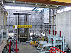
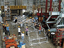
Structures including skyscrapers, mighty long bridges and large ships, are increasingly becoming bigger and more complex. The laboratory was completed in December 1975 after five years of survey and research for studies on structural dynamic behaviors that underlie the designs of these structures. The test space is broadly divided into a structure testing machine, test floors equipped with reaction wall, and an off-laboratory test field. The structure testing machine has a large test space with a maximum compressive test load of 30MN and tensile test load of 10MN, and its main pillars have a large interval of inside measurement. The Test Floor A that has test rigs installed on its floor is a space where loads can be applied to test samples by jacks, and a test frame that follows the size of test sample is available on this test floor. A variety of tests can be preformed on this floor by using the reaction force walls in combination with structure fatigue testing machine and artificial dynamic testing machine, which are designed to identify the behaviors of structures against static and dynamic external forces. The Test Floor B is equipped with a multi-input vibration testing machine to identify the earthquake resistance of structures with high precision. The off-laboratory test field is a test environment available for construction tests of structures, and fabrication and erection of test samples, among others. There are many structure testing facilities equipped with structure testing machines in Japan and elsewhere. This laboratory, however, boasts the largest scale among those built by universities.
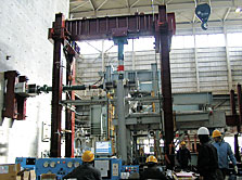
30MN LARGE-STRUCTURE TESTING MACHINE
The studies on dynamic behavior in structure designs have been advanced by dynamic test and analysis of structures to. In the field of theoretical analysis, the advance of technology due to sophistication in computers has made it possible to perform complex structure analysis, Likewise highly sophisticated techniques are also required for tests to support such complex analysis. In the nonlinear range, including the plastic range of materials, it is often impossible to infer the behavior of real structures from analogy with structure models. In some cases, it is actical to set aside theories and build real structures. In such a case, tests on full-size or nearly full-size samples are required, and testing machines have to proportionally become larger. This machine was built by Shimadzu Corp. Specifically for such purposes . It took about eight months to work out the specifications, and about three years from design to delivery.
 Major Research Topics
Load cell calibration test
Calibration of hydraulic jack
Compression test of high-strength reinforced concrete pile
Compression test of propulsion pipe
Punch-out strength test of taper cone
Research on structure system of hollow-body structural member
Safety test of temporary scaffolding
Performance assessment of base-isolation laminated rubber support
Buckling test of steel strut
Bending test of slide joint
Tensile-strength and breaking test of cruciform joint
Tensile test of junction joint
 Japan's large-structure testing machines
30MN 1975 Department of Science and Technology, Nihon University
30MN 1977 Public Works Research Institute of Ministry of Land, Infrastructure and Transport
 Main Characteristics
| Maximum capacity | Compression Tension Bend |
30MN 10MN Right bend 6MN Reverse bend 3MN |
|---|---|---|
| Load range | 30MN, 12MN, 6MN, 3MN, 1.2MN | |
| Load measurement method | Measurement of internal pressure in cylinder | |
| Main pillar | No. of pillars Dimensions of inside measurement |
4 3×3.6m |
| Ram | Position No. of rams, Stroke |
Lowe ram 4 for compression and 1 for tension, 1m |
| Interval of pressure boards | Maximum 10m | |
| Bed | Dimensions, Level | 22m in X direction and 10m in Y, direction |
| Test space | Continuous loading in compression and tension directions is possible. |
TEST FLOOR AND REACTION WALL
Dve to frames and threaded spindles, the sizes of test samples are limited. There are other constraints in the case of dual- and three-axis loads. For these reasons, the frames are fixed on the floor through threaded holes, and the needed loads are applied to test samples by several jacks. As for the loads in a horizontal direction like earthquake loads, the reaction forces are absorbed by the reaction wall that are integral with the Test Floor. Such walls are called reaction wall. In other words, test samples are built in proportion to the testing machine in the structure of testing machine, while the loading machine is configured in proportion to test samples on the Test Floor. Almost all of the structure testing facilities in Japan and elsewhere are equipped with such test floors and reaction wall. The screw hole in the Test Floor have the capacity of 500kN per point, and the reaction wall have the capacity of 3MN in horizontal force and 12MN per meter in moment.
 Major Research Topics
Experimental research on resilient characteristics of prestressed membranes and concrete members
Experimental research on the size effect of reinforced concrete beams under bending
Research on joints of structural systems built by hollow-body prestressed membrane and concrete membranes
Construction and load tests of tensile-film structure
Strength test of full-size structure unit of residential building to be constructed at the Showa Base in the Antarctic
Research on the methodology of fixing reinforced foundations for houses
Load test of steel hybrid floor panel
Experimental research on floating bridges
 The Structural Vibration Testing Machine with Multi-channel Exciting
| Horizontal uniaxial vibrating table (2 sets) |
Horizontal two-axial vibrating table |
|
|---|---|---|
| vibrating table | 2.5m(excitation direction)×1.5m | 2.5m×2.5m |
| Excitation force | 75kN | X-axis 100kN Y-axis 150kN |
| Permissible overturning moment | Excitation direction 70kN-m Right-angle direction 20kN-m |
X-axis 70kN-m Y-axis 70kN-m |
| Permissible rotation moment | 50kN-m | |
| Maximum displacement | ±200mm | |
| Maximum acceleration | 1.2G(3t-loaded condition) 1.0G(5t-loaded condition) | |
| Acceleration and duration | Average speed35cm/sec(sinusoidal excitation condition) | |
| Frequency range | 0.01Hz~50Hz | |
| Maximum loading weight | 5t | |
| Supportive direction of the table |
Hydrostatic bearing system | |
| Input waveform | Sinusoidal wave, arbitrary irregular wave(Practical vibration record, artificial seismic wave, random wave) | |
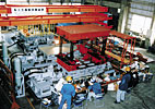
THE STRUCTURAL VIBRATION TESTING MACHINE WITH MULCI-CANNEL EXCITING
This testing machine was built (by Shimadzu Corp.) to establish a methodology that identify, with high precision, any different types of earthquake inputs, if any, into each support strut of a structure. It is composed of one horizontal dual-axis shaking table, and two horizontal single-axis shaking table. Each of these shaking tables can be shaken respectively by different waveforms. A displacement of a large span structure between support struts can be duplicated by horizontally shaking the two single-axis shaking tables, and an elastic displacement can also be duplicated by moving one of the two single-axis shaking tables and placing them in a line. Moreover, the combination of the three shaking tables makes it possible to create a state in which seismic waves input successively into the three support struts. (This multi-input vibration testing machine was built together with a multi-input artificial dynamic testing machine by the Japan Science Society as part of its "Research on Commercialization of Torapolis" project with subsidies from the Japan Shipbuilding Industry Foundation, and transferred in November 1991.)
 Major Research Topics
The Structural Vibration Testing Machine with Multi-channel Exciting:
Verification of performance of quake control system
Confirmation and assessment of earthquake resistance
Vibration test of base-isolation system
Experimental research on response properties of friction damper
Research on sliding-friction-type base-isolation structure
Research on measurement of low-pass frequency
Multi-input pseudo-dynamic testing machine:
Experimental research on shearing properties of prestressed membranes and concrete membranes
Characteristics of members of steel-frame pillars
Research on shearing and deformability of wooden panels for use at the Showa Base in the Antarctic
Structure Fatigue Testing Machine:
Dynamic load test of shaped post-and-beam joints of reinforced concrete structures
Research on load response characteristics of metal structures
Research on dynamics of rubber fender beams
Area outside the test field:
Erection and load tests of tensegrity bridge
Research on aged deterioration of buildings that use thinned woods
 More Info
http://www.str.cst.nihon-u.ac.jp/
Inquiry
Funabashi Campus
TEL:+81-47-469-5362
E-mail:office@str.nihon-u.ac.jp


